
Hierarchical Graph Representations for Configuration Space in Modular Reconfigurable Robots
Defining the Configuration Space
There is a quote by Linus Torvalds, creator of Linux, Git, and other fundamental pieces of software, that says “Bad programmers worry about the code. Good programmers worry about data structures and their relationships.” I think that a similar idea might hold in metric development. If a good data structure for representing configurations of MRRs is established, the measures we wish to find for reconfigurability may present themselves.
I have spent a lot of time lately thinking about how to define reconfigurability in the context of modular reconfigurable robots (MRRs). It is fairly common to represent a single MRR with a graph structure, but that only represents a single configuration. It doesn’t encode the set of possible configurations nor any sort of relationships between them. I believe that one of the ideas that may be fundamental to defining reconfigurability is the distance between two configurations.
Take the six possible connected graphs on four vertices labeled $C_1$ to $C_6$:
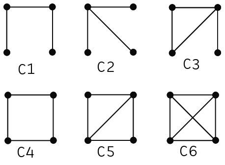
A reconfiguration from $C_n$ to $C_m$ will be denoted $R_{nm}$
Imagine a four module MRR changes from configuration $C_1$ to configuration $C_4$, meaning it performs reconfiguration $R_{14}$. What if instead that same MRR performed reconfiguration $R_{16}$. Which is a “larger” reconfiguration? Intuitively, the answer may be clear that $R_{14}$ is smaller than $R_{16}$. A more robust way to analyze this may be to count the number of reconfiguration actions required to reconfigure from one configuration to another. A reconfiguration action in this case would be edge deletion or edge creation since these represent modules connecting or disconnecting from each other.
The reconfiguration actions required for $R_{14}$ are as follows:
- Create one edge between the two vertices of degree 1
A valid sequence of reconfiguration actions for $R_{16}$ are as follows:
- Create one edge between the two vertices of degree 1
- Create one edge between two non-adjacent vertices
- Create a final connection between the remaining non-adjacent vertices
Note that $R_{14}$ exists within the reconfiguration steps for $R_{16}$. An interesting way to represent these reconfigurations then might be a graph structure. This hierarchical graph represents the valid configurations of the MRR as the vertices and the reconfiguration actions to move from one configuration to the next as edges. This will be referred to as the configuration space graph, sometimes referred to as a transition graph [2]. This makes it simple to represent the possible configurations for a MRR. Additionally, it allows for computation of distance between configurations by computing minimum graph distance. For simplicity sake, all isomorphic graphs are considered to be identical. This may be a valid assumption for a homogenous MRR.
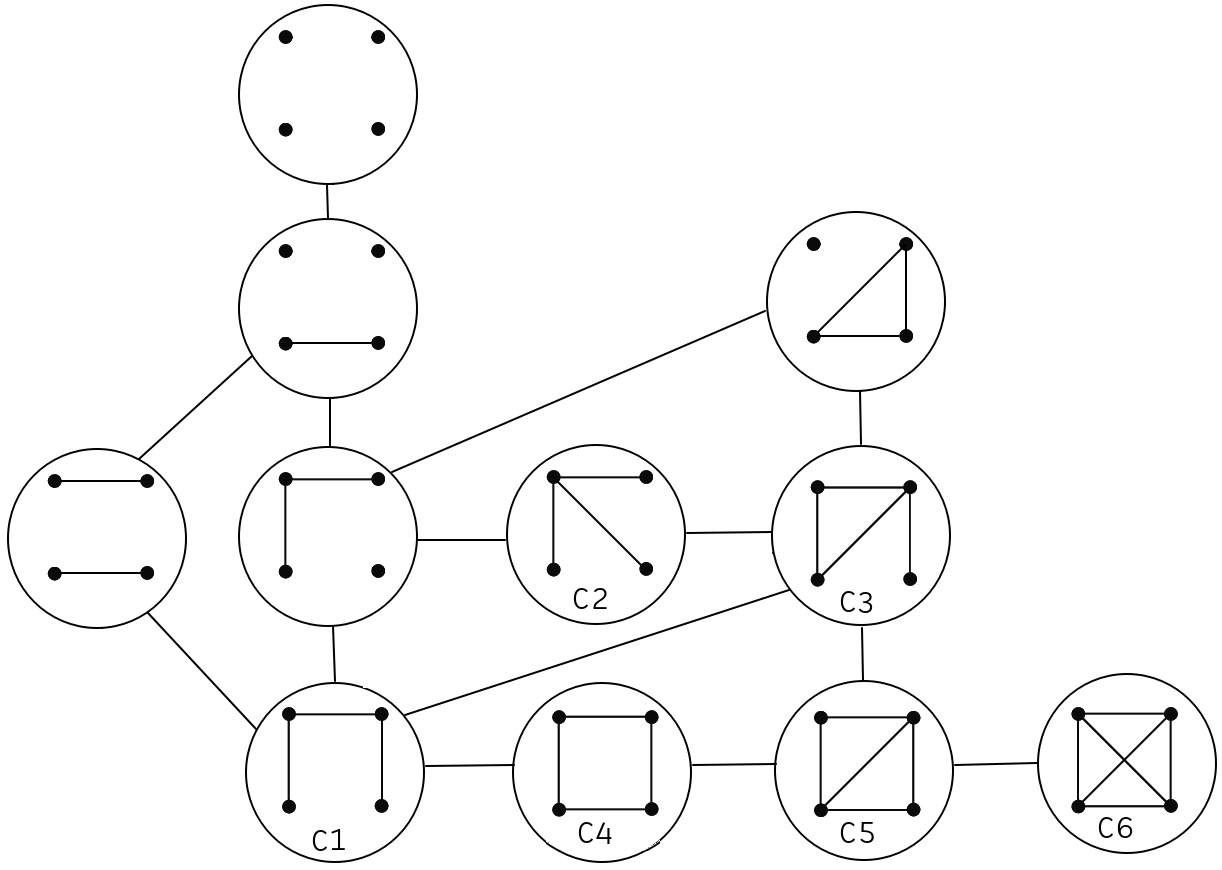
It then becomes very clear that the distance between $C_1$ and $C_4$ is less than the distance between $C_1$ and $C_6$. This representation also allows us to see the distances between any two arbitrary configurations. The idea of using graphs to represent configuration space is not novel. It has been used in the past to enumerate and search the configuration space for valid paths [3]. It should be noted that the number of vertices in the transition graph grows exponentially as the number of modules in the system increases. For this reason, numerical optimization methods such as simulated annealing have been used to search for near optimal reconfiguration paths [3].
Graph Invariants for Analysis of Reconfigurability
Now imagine the C-Space graph is weighted. What might these weights represent? That could easily be context dependent. Perhaps each edge contains a set of data including estimated reconfiguration time, estimated reconfiguration energy use, or probability of failure of this particular reconfiguration. Then higher level decisions can be made at the planning level about which reconfiguration paths result in the fastest reconfiguration, or the least energy consumption, or the highest probability of success. Whatever is important based on the task at hand.
In computer networks, there is not a concrete, agreed upon definition of robustness [4]. It is common to utilize a number of graph based metrics including connectivity, vertex connectivity, edge connectivity, diameter, average distance, graph efficiency, maximum edge betweenness, average vertex betweenness, average edge betweenness, clustering coefficient, algebraic connectivity, number of spanning trees, or effective graph resistance [4]. It is possible that the idea of reconfigurability in modular reconfigurable robotics is similar. Perhaps a number of different metrics will be used to define different ideas about reconfigurability. A few potential metrics are listed in the table below:
| Configuration Space Graph Metric | Definition | Information about MRR |
|---|---|---|
| Number of vertices | - | Number of reachable configurations |
| Diameter | The longest distance between any pair of two vertices | The maximum number of required reconfiguration actions between any two configurations |
| Betweenness Centrality | The number of shortest paths between pairs of vertices, passing through a vertex or an edge | Importance of a particular configuration for reaching other configurations |
| Algebraic connectivity ($\lambda_2$) | The second eigenvalue of the Laplacian matrix | If $\lambda_2 = 0$, the graph is disconnected and some configurations are unreachable |
Some other metrics may be useful when applied to the configuration graph instead. For example, if we look at the number of non-isomorphic spanning trees that exist in a maximally dense configuration graph for a MRR, that might give information about the number of unique chain configurations that can be reached.
Citations
[1] X. Liu and P. Lu, “Signless Laplacian spectral characterization of some joins,” The Electronic Journal of Linear Algebra, vol. 30, p. 443, Feb. 2015, doi: 10.13001/1081-3810.1942.
[2] H. Y. K. Lau, A. W. Y. Ko, and T. L. Lau, “The design of a representation and analysis method for modular self-reconfigurable robots,” Robotics and Computer-Integrated Manufacturing, vol. 24, no. 2, pp. 258–269, Apr. 2008, doi: 10.1016/j.rcim.2006.11.003.
[3] A. Pamecha, I. Ebert-Uphoff, and G. S. Chirikjian, “Useful metrics for modular robot motion planning,” IEEE Trans. Robot. Automat., vol. 13, no. 4, pp. 531–545, Aug. 1997, doi: 10.1109/70.611311.
[4] W. Ellens and R. E. Kooij, “Graph measures and network robustness,” Nov. 07, 2013, arXiv: arXiv:1311.5064. doi: 10.48550/arXiv.1311.5064.